There are many projects and tutorials related to recycle old CD/DVD players into a mini CNC Plotter based on Arduino.

I have become too concerned with complicated details or new things, and now I should concentrate on basic, simple and important ideas. Getting back to basics, to start learning CNC, today I'd like to share how to easily build your own low-cost Arduino Mini CNC Plotter. With my version, I used the spring part of stapler as a main component for pen lift. During the process of doing this, I have referenced from many sources, studied & tried to clarify some point hard to grasp.
Let's getting started.
Step 1: THINGS WE NEED
Main components:
1pcs x CNC Shield V4.
1pcs x Arduino Nano.
2pcs x Stepper Motor Driver A4988.
2pcs x Old CD/DVD Players.
1pcs x Servo Motor SG90.
1 meter x 8P Rainbow Ribbon Cable.
1pcs x Aluminium Angle 20 x 20 x 1.4mm - Length 120mm.
1pcs x Stapler.
1pcs x Power Supply 12V.
1pcs x Aluminum Flexible Shaft Coupling, Inner Hole Size: 5mm x 8mm (or 8mm x 8mm).
2pcs x Copper Brass Pillars L-10mm.
2pcs x Copper Brass Pillars L-5mm.
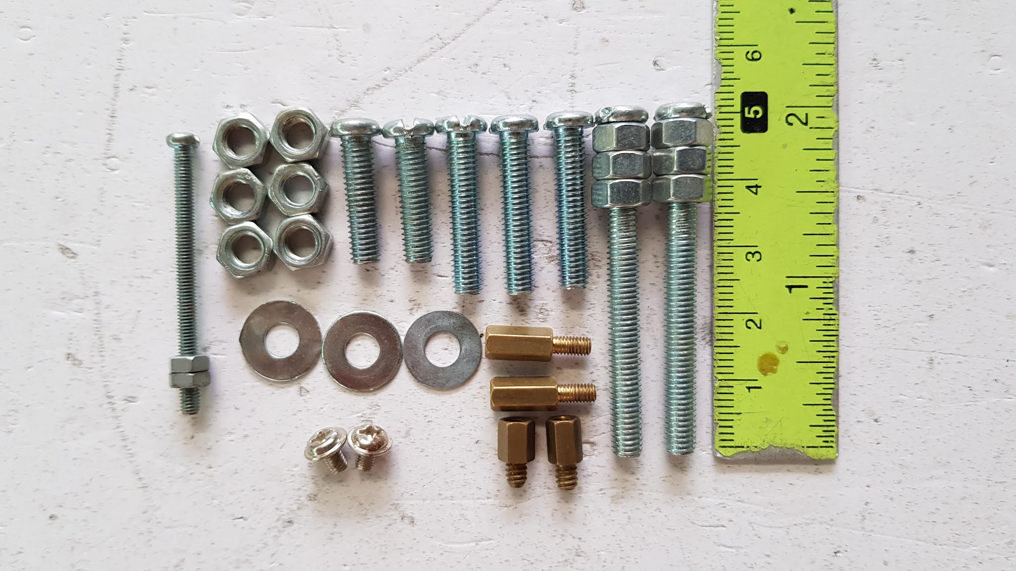
2pcs x Bolts + Nuts + Washers M4 x 50mm.
3pcs x Bolts + Nuts + Washers M4 x 25mm.
2pcs x Bolts + Nuts + Washers M4 x 20mm.
1pcs x Bolts + Nuts + Washers M2 x 40mm.
2pcs x Bolts + Nuts + Washers M2 x 5mm.
Some small cable ties.
Tools:
Sawing Machine.
Drilling Machine.
Hand Grinder.
Hot Glue Gun.
Soldering Machine.
Softwares:
MIGRBL firmware.
INKSCAPE version 0.48.5.
INKSCAPE MI-GRBL Extension.
Universal Gcode Sender.
Step 2: IDEAS
The idea to build a mini CNC plotter is simple: use two old stepper motor-controlled CD/DVD player, one is used as a plotting surface that moving forward and backward - Y axes, and mount the other vertically on it to provide left and right movement - X axes. Then we mount a RC servo to X axes to lift the pen up and down during plotting- Z axes.
Step 3: DVD/CD DRIVE STEPPER MOTORS
DVD/CD drive stepper motor specifications
It is difficult to find the exact specifications of these steppers. I found the specs of DVD/CD stepper motor which is similar to mine on the internet. The important parameters are highlighted in orange.
http://www.oncetop.com/Products/OTSM15L013Stepperm...

I tried to open a broken stepper motor to see the details inside. You can check the picture below:DVD/CD drive stepper motor disassembly

The stepper operate at 5VDC, we should measure 2 coils resistance by a multimeter to check whether it is in good condition.
I had two different types of DVD/CD players, one was used for the X axis with coil resistance of stepper motor 14Ω and the other was used for the Y axis with 10Ω coil resistance.
Step 4: CNC SHIELD V4.0
CNC Shield V4.0 has 3 slots on the PCB board for stepper motor drive modules and one slot for Arduino Nano. It can drive 3 stepper motors by Arduino Nano. CNC Shield V4.0 has some GPIO pins available for connecting to other modules, like limit switch, as well as, I2C interface or serial communication. Power for 3 stepper motor drive modules and Nano board is supplied via an external power jack (DC 12V).
I bought the CNC shield V4 with cheap price from China. Through references, I found that I had to adjust both hardware and software in order to use GRBL firmware and set up the micro-steps mode for A4988. I have applied the methods below:
https://www.instructables.com/id/Fix-Cloned-Arduin...
A. FIX THE HARDWARE:
The jumpers to configure the number of micro-steps are all connected to GND while they need pulling up to VCC. The micro-step value is fixed at low levels and always put stepper driver in full step resolution.
BOTTOM VIEW

TOP VIEW

B. FIX THE SOFTWARE:
The pins connected to the "STEP" and "DIRECTION" inputs of the stepper drivers are wrong in comparison with the original GRBL definitions. CNC Shield V4.0 use Arduino Nano so we can correct "STEP" and "DIRECTION" pins definitions in file "cpu_map_atmega328p.h" located in the grbl folder, as follows:
#define X_STEP_BIT   5  // Uno Digital Pin 2
#define Y_STEP_BIT   6  // Uno Digital Pin 3
#define Z_STEP_BIT   7  // Uno Digital Pin 4

#define X_DIRECTION_BIT   2  // Uno Digital Pin 5
#define Y_DIRECTION_BIT   3  // Uno Digital Pin 6
#define Z_DIRECTION_BIT   4  // Uno Digital Pin 7
Step 5: STEPPER MOTOR DRIVER A4988
The A4988 is a complete microstepping motor driver with built-in translator for easy operation. It is designed to operate bipolar stepper motors in full-step, half-step, quarter-step, eighth-step, and sixteenth-step modes, with an output drive capacity of up to 35V and ±2A.
We can control the stepper motor with just 2 pins from our controller, like Arduino: one for controlling the rotation direction and the other for controlling the steps.
A. MICRO-STEPPING SETTINGS
In many applications, micro-stepping can increase system performance, and lower system complexity and cost, compared to full-step and half-step driving techniques. Micro-stepping can be used to solve all resonance, vibration and noise problems in a stepper motor system, and to increase step accuracy and resolution.
The rules is, the more micro-steps, the smoother motions but lower the torque and and vice versa. I had tried with 1/16 micro-steps but finally, I chose 1/8 micro-steps which is a good combination between smooth motion and torque.
Each rotation of DVD/CD stepper is originally divided into 20 steps with angle 18°/step (1 rotation = 360 degrees | 360 / 20 = 18°). When we apply micro-stepping mode with 1/8 step resolution on A4988 to control this stepper, each rotation of DVD/CD stepper will be divide into 160 steps with angle 2.25°/step, making the rotation of the stepper motor much smoother.

My micro-steps setting is 1/8 step resolution for both X and Y axis stepper motors:

B. CURRENT LIMITING
The trimmer potentiometer on the A4988 board can be used to set the current limit of stepper. We should pay attention to the following steps:
The A4988 stepper driver boards use various current sense resistors RCS depending on the manufacturers, usually RCS can be 0.05Ω (labeled with "R050"), 0.1Ω (labeled with "R100") or 0.2Ω (labeled with "R200"). The RCS on my A4988 control board is: 0.1Ω.
The CD/DVD steppers operate at 5V voltage level, we could measure 2 coils resistance with a multi-meter to get an estimated max current using Ohm’s law: IMAX = V/R.
The current limit, IMAX, relates to the reference voltage as follows: VREF = (8 * IMAX * RCS).
My calulation sheet for X and Y stepper motors:

X AXIS STEPPER: VREF = 286mV.Following above calculation sheet, my final current limit settings for 2 stepper are:
Y AXIS STEPPER: VREF = 400mV.
To calculate VREF required for a target current A, we can apply the following simple formulas:
VREF = A/2.50 with RCS = 0.05Ω.
VREF = A/1.25 with RCS = 0.10Ω.
VREF = A/0.63 with RCS = 0.20Ω.
Step 6: ASSEMBLY
A. MOUNTING X & Y AXIS
There have been a lot of instructions for making X and Y axis - mini CNC plotter. For this project, I mainly used bolts to connect components together.
First step to start building this Mini CNC Plotter is to disassemble two DVD/CD drives.
I soldered the 4 wire cables to 2 stepper motors after identifying their windings and terminal wires.
I measured the length of the DVD / CD player - X axis that will be arranged horizontally, then I cut aluminum angle 20 x 20 x 1.4 mm with the corresponding measured length. In my case it's 120mm long.
I drilled a total of 6 holes in this aluminum angle as follows:
- Two holes are bolted to the DVD / CD drive of Y-axis by M4x50.
- Two holes are bolted to the DVD / CD drive of the X-axis by M4x25.
- Two remaining holes are connected to CNC Shield V4.0 via copper brass pillars L-10mm.

For Y axis - plotting surface, I used one stainless steel plate with dimension 70 x 80 mm.

The picture below shows the stand of the mini CNC plotter.

B. MOUNTING Z AXIS
I have referenced to many projects on how to do the pen lift mechanism and it seems to be the most important & hardest part when building a CNC mini plotter. When I used staplers at my office, I came up with the idea that I could use the stapler as the mechanical part to lift the pen. And it is really effective. If you had trouble of building a pen lift of mini CNC plotter, you can refer my instructions below. It is easy to do with the available office supplies.
A stapler is an incredibly useful tool that is mostly found in offices and your own home. It's used to fasten together sheets of paper with staples. In this project, I used the stapler's spring mechanism to move pen up and down of Z axis.
Firstly I disassembled the stapler into small components.

The middle part is stapler's magazine cartridge with pushing block and spring, it has 2 small holes with distance 17 mm. I used it to mount the pen/ pencil.

I connected them to 2 holes of the flexible coupling 5 x 8 by 2 screws + 2 copper brass pillars to hold the pen/pencil.

Since the thread pitch of flexible coupling hole differs from the common copper brass pillar, I have to used the cooper brass spacer taken from the broken computer. Its head is bigger than common one. You can check its picture below.

Take note, to ensure the stapler spring do not touch the head of the screws when the pushing block moving up and down, I grinded the head of two screws as thin as possible.

RC servos is fitted well into the inner U-shaped frame of stapler.

I removed the plastic part, cut and kept only the U-shaped part to clamp RC servo.

Connect RC servo and pushing block together by long screw M2 x 40 through 4 holes of stapler. I tightened it to make sure the servo couldn't move when it worked.

On the back side of stapler's magazine cartridge, there is one big hole. Later it will be used to connect pen/pencil holder including RC servo to the X axis mechanism through this hole by bolt M4x25 & 3 nuts.

Put the pencil into the flexible coupling and do aligning and tightening. To clamp the pen, we can tighten 2 remaining small screws on the flexible coupling. To lift the pen, I cut the rubber or acrylic sheet in round shape, drill a hole in the center with same pen's diameter. I mounted it on the pen, adjust it comparing with RC servo arm so that the pen can be lifted up by RC servo arm and down by stapler spring smoothly.

And here below is the ballpoint pen version


C. FINAL ASSEMBLY
I connected, aligned and tightened pen lift part to DVD/CD drive - X axis by bolt and nuts.

I mounted CNC Shield V4.0 to aluminium angle at 2 copper brass pillars and connected all cables of 2 stepper motors, RC servo to CNC shield. Then I used some cable ties to fix the wires and made it tidy.

Done.

Step 7: UPLOAD MIGRBL FIRMWARE TO ARDUINO NANO
MIGRBL differs from original GRBL in that MIGRBL is customized for CNC shields that have the X and Y axes connected to 2 stepper motors and the Z axis connected to a RC servo motor for pen lifting up/ down.
Download MIGRBL firmware files.
Copy MIGRBL to C:\Users\Administrator\Documents\Arduino\libraries\
Do correction following STEP 4 - B. FIX THE SOFTWARE.
Now that we have installed the MIGRBL library on the IDE and did the nessessary correction. Open Arduino IDE, from File menu click Examples --> MIGRBL --> grblUpload.
Select the correct port and board (Arduino Nano), compile and upload the code to Arduino Nano.
With my Arduino Nano, I had to select via the Arduino IDE's Tools --> Processor --> ATmega328P (Old Bootloader) after choosing Tools --> Board --> Arduino Nano.
We can learn more about GRBL at below site: https://github.com/gnea/grbl/wiki
Step 8: INSTALLING INKSCAPE & INKSCAPE MI-GRBL EXTENSION
I used INKSCAPE software to generate the G-code.
Downloaded INKSCAPE version 0.48.5 software.
Installed it to my computer.
Because I used MIGRBL firmware for Arduino Nano (plugged on CNC Shield V4.0) for this mini CNC plotter and Axis Z – pen lift is controlled by RC servo motor, so the normal G-CODE generated from INKSCAPE will not work. In order for it to work, we do the following steps:
Download the INKSCAPE MI-GRBL EXTENSION.
Unzip the file.
Copy the uncompressed files to the INKSCAPE directory --> Share --> Extension folder.
Step 9: INSTALLING GRBL CONTROLLER APPLICATION
After we have an executable G-code file from INKSCAPE, to stream and send G-CODE file to Arduino Nano, we can use Universal Gcode Sender - UGS.
Download the UGS software at: https://winder.github.io/ugs_website/download/, then install it to computer.
Open UGS, select Port and set Baud to 115200.
Click on "Connect" then we can see in "Console" tab the following information are displayed.

Step 10: CALIBRATION WORKS
STEPS/MM: Tells GRBL how many steps are required to move the machine a given distance.
Steps/mm = (Steps per Revolution)*(Micro-steps) / (mm per Revolution)
Steps per Revolution = 20 - This is the original number of steps required for the stepper motor to make 1 complete revolution.
Microsteps - 1, 1/2, 1/4, 1/8, 1/16 - This is a setting on the stepper motor driver A4988. A higher value means lower torque but higher accuracy. My Micro-steps setting is: 1/8.
mm per Revolution - This is distance in mm the screw moves in one revolution (screw pitch). Because CD/DVD ROM stepper's screw is a "single-start" type, so the "pitch" is the axial distance between adjacent threads.
| The total length of the screw: | 51.56 | mm |
| The working length of the screw: | 40.00 | mm |
| The threads counted in the working length: | 13 | - |
| Step angel: | 18 | ° |
| The number of steps required for DVD stepper to make 1 complete revolution: | 20 | step/rev |
| A4988 micro-steps setting: | 8 | - |
| DVD stepper screw pitch (mm/revolution): | 3.0 | mm/rev |
| STEP/MM: | 53.333 | step/mm |
According to the specifications, the screw pitch of DVD/CD stepper motor is 3mm. We can check by measuring the working length of the screw: 40mm and count the number of threads in this working range: 14. The screw pitch can be estimated as follows:
PITCH = 40/13 = 3mm.
My final calibration:
X Max travel (mm): $130 = 40.000
Y Max travel (mm): $131 = 40.000
X steps/mm: $101 = 53.333
Y steps/mm: $100 = 53.333
These above values worked precisely by my tests.
Step 11: START TO USE
We could pay attention the following steps before put the mini CNC plotter into operation.
Check the A4988 micro-steps settings: detail description at STEP 5.
Check the A4988 current limiting settings: detail description at STEP 5.
Connect the mini CNC plotter to UGS and check its calibration parameters: detail description at STEP 10.
To test the motors and the CNC Shield, go to the Machine Control tab --> Click on the arrows X+, X-, Y+ and Y-.
We should keep tracking the stepper motors moving, touch on them to check whether they are hot. If stepper motors were hot, we should double check the VREF on A4988 by multimeter and lower down a bit the VREF.
Correct the direction of this plotter is as follow: An easy way to understand the Cartesian coordinate system in relation to your CNC machine is using the "Right Hand Rule".

We can changes axis motion direction without changing wiring at Axis Direction $3. Due to my stepper motors arrangement, I had to reverse the direction of the Y - axis stepper, so my setting value was: $3 = 2. See Axis Configuration Table below.
| Setting Value | Reverse X | Reverse Y | Reverse Z |
| 0 | 0 | 0 | 0 |
| 1 | 1 | 0 | 0 |
| 2 | 0 | 1 | 0 |
| 3 | 1 | 1 | 0 |
| 4 | 0 | 0 | 1 |
| 5 | 1 | 0 | 1 |
| 6 | 0 | 1 | 1 |
| 7 | 1 | 1 | 1 |
INKSCAPE:
- Open INKSCAPE.
- Set page size to 40 x 40mm.
- Draw a square with diemension 10 mm x 10 mm --> Select Image --> Convert to Path
- Go to Extension Menu --> Click on MIGRBL Z-AXIS SERVO CONTROL , adjust the values on the pop-up box. My setting is showed on the picture below:

- Click on Apply, the square G-code is saved with a name & at the folder we chose.
Universal Gcode Sender
- Open UGS, select Port and set Baud to 115200, click on "Connect" tab.
- Select the appropriate position by moving X axes left - right, Y axes forward - backward and set the original coordinates by button "Reset Zero".
- Click "Open" --> Browse to the G-code file that generated by INKSCAPE.
- Click "Send" and mini CNC will perform drawing square 10x10 mm following the G-code.
- Monitor the mini plotter in action on the "Visualizer" tab.
- Measure the actual length in X and Y axes by ruler to see if 10mm was correct. If not, we should check the step/mm or any mechanical parts get stuck.
- Draw some more circles with different diameters, check if the start and end point of the circle coincide? If it does not coincide, it is possible that the pen tip is skewed, or the mechanical parts are not aligned.
Step 12: FINISH
You can see some pictures of this project. My mini CNC plotter works pretty good although I know that it need to be more fine-tuned.


Watch the video for instruction:
0 Comments: