 |
This project uses L298 (known as H-bridge) to run brushless motor (taken from HDD) via Arduino Pro Mini. By this project, we also know how brushless works
1. PCB H-bridge L298 (2pcs)
2. Arduino Pro Mini
3. Brushless motor (take from HDD)
 |
| 1. H-Bridge L298 |
 |
| 2. Arduino Pro Mini |
1. Understand brushless motor principle
 |
| Image of brushless motor of HDD |
Motor stator will make magnetic field -> when magnetic direction moving -> it will move rotor
Let's see how magnetic field moving:
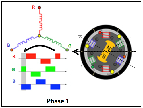
At "phase 1", power (+) is applied to Green coil, and power (-) is applied to Blue coil -> sum of vector magnetic field of Green coil and Blue coil will make magnetic direction as in above picture (horizontal direction) -> this magnetic field will make rotor rotating and align to magnetic direction, then stop at this direction
To move rotor, magnetic field must moving -> see "phase 2"

Continue with phase 3, 4, 5, 6 -> magnetic field rotates 1 circle -> rotor also rotates 1 circle


2. Driver for brushless motor
A Driver for brushless motor is used to arrange power (+) and power (-) synchronizing to each coil Blue, Red, Green for rotating magnetic field
Following table is summarize of power (+) and power (-) need to apply each coil at each phase:
Phase
|
1
|
2
|
3
|
4
|
5
|
6
|
Blue
|
-
|
-
|
N
|
+
|
+
|
N
|
Red
|
N
|
+
|
+
|
N
|
-
|
-
|
Green
|
+
|
N
|
-
|
-
|
N
|
+
|

3. Connection to L298 H-bridge
Half of H-bridge is used to connect to each coil of brushless motor
Look inside L298 IC -> it is possible to flow current from half H-bridge to another half H-bridge

4. Circuit connection

Schematic diagram by Fritzing:

ENA IN1 is connected to H-bridge 1
ENB IN3 is connected to H-bridge 2
ENC IN1 is connected to H-bridge 3
This project need 3 half of H-bridge -> need 2 L298 PCB. Here is my result connection:
|
| Result of connection |
For this connection, we have pattern code as here:
Phase
|
1
|
2
|
3
|
4
|
5
|
6
|
Blue
|
-
|
-
|
N
|
+
|
+
|
N
|
Red
|
N
|
+
|
+
|
N
|
-
|
-
|
Green
|
+
|
N
|
-
|
-
|
N
|
+
|
ENA
|
1
|
1
|
0
|
1
|
1
|
0
|
IN1
|
0
|
0
|
0
|
1
|
1
|
0
|
ENB
|
0
|
1
|
1
|
0
|
1
|
1
|
IN3
|
0
|
1
|
1
|
0
|
0
|
0
|
ENC
|
1
|
0
|
1
|
1
|
0
|
1
|
IN1
|
1
|
0
|
0
|
0
|
0
|
1
|
5. Coding for Arduino
/*
 Motor - brushless motor control
 Created 07 Jan. 2018
 This example code is in the public domain.
 http://engineer2you.blogspot.com
 */

const byte en_A = 2;
const byte in_A = 3;
const byte en_B = 4;
const byte in_B = 5;
const byte en_C = 7;
const byte in_C = 8;

int speed_motor = 20;

void setup() {
  pinMode(en_A,OUTPUT);
  pinMode(in_A,OUTPUT);
  pinMode(en_B,OUTPUT);
  pinMode(in_B,OUTPUT);
  pinMode(en_C,OUTPUT);
  pinMode(in_C,OUTPUT);

  // start serial port at 9600 bps:
  Serial.begin(9600);
  while (!Serial) {
    ; // wait for serial port to connect. Needed for native USB port only
  }
}

void loop() {
  //increasing speed gradually by loop
  for (int i = 0; i<=(21-speed_motor)*5; i++) {
    motor_run();
  }

  if (speed_motor > 2) speed_motor = speed_motor - 1; //increasing speed
  Serial.println(speed_motor);  //print out speed to serial port
}

void motor_run() {
  digitalWrite(en_A,1);
  digitalWrite(in_A,0);
  digitalWrite(en_B,0);
  digitalWrite(in_B,0);
  digitalWrite(en_C,1);
  digitalWrite(in_C,1);
  delay(speed_motor); //Phase 1
  digitalWrite(en_A,1);
  digitalWrite(in_A,0);
  digitalWrite(en_B,1);
  digitalWrite(in_B,1);
  digitalWrite(en_C,0);
  digitalWrite(in_C,0);
  delay(speed_motor); //Phase 2
  digitalWrite(en_A,0);
  digitalWrite(in_A,0);
  digitalWrite(en_B,1);
  digitalWrite(in_B,1);
  digitalWrite(en_C,1);
  digitalWrite(in_C,0);
  delay(speed_motor); //Phase 3
  digitalWrite(en_A,1);
  digitalWrite(in_A,1);
  digitalWrite(en_B,0);
  digitalWrite(in_B,0);
  digitalWrite(en_C,1);
  digitalWrite(in_C,0);
  delay(speed_motor); //Phase 4
  digitalWrite(en_A,1);
  digitalWrite(in_A,1);
  digitalWrite(en_B,1);
  digitalWrite(in_B,0);
  digitalWrite(en_C,0);
  digitalWrite(in_C,0);
  delay(speed_motor); //Phase 5
  digitalWrite(en_A,0);
  digitalWrite(in_A,0);
  digitalWrite(en_B,1);
  digitalWrite(in_B,0);
  digitalWrite(en_C,1);
  digitalWrite(in_C,1);
  delay(speed_motor); //Phase 6
}
0 Comments: